
Overview
Increasing turbine inlet temperatures and the lowest possible cooling air consumption require the use of efficient cooling technologies. This is not only relevant in the combustion chamber, but also in the downstream turbine stages, especially the first row of guide vanes and rotor blades directly downstream of the combustion chamber. Only through intensive convective heat transfer in and on the back of the components to be cooled can the wall temperatures be brought into acceptable ranges. The surface temperatures of film-cooled turbine blades are essentially determined by the convective heat transfer on the cooling air side. As a result of advanced manufacturing processes such as single-crystal casting, but also additive manufacturing, the increase in convective heat transfer can be taken into account by adding turbulators (pin fins, ribs, dimples, etc.) to the side of the blade facing the cooling air. In the latest generation of engines, these turbulators are integrated in various designs within the gap of a double-walled monocrystalline high-pressure turbine vane, which is only a few tenths of a millimeter wide.
These highly thermally stressed components and thus also the fine structures within the blade are subject to complex stresses from thermal and thermomechanical fatigue, creep and corrosion, which place the highest demands on the nickel-based superalloys used for this purpose. Even if today's materials have sufficient strength and ductility as well as a low creep tendency and high corrosion resistance with comparatively low density, their high thermal expansion coefficients and low thermal conductivity lead to thermally induced alternating stresses. Despite adequate cooling, these contribute significantly to component failure due to thermal fatigue.
The alternating stresses result from the different hot gas temperatures at the turbine inlet during a flight cycle. In particular, take-off and thrust reversal during landing contribute to high transient temperature gradients and the associated thermal stresses within the component due to the rapid change in turbine inlet and cooling air temperatures, which lead to thermal fatigue.
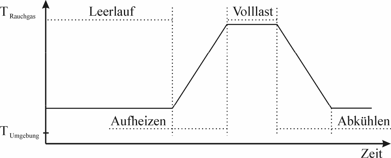
Furthermore, it has been shown that these stresses vary considerably over time, but also locally, and are much higher than induced steady-state thermal stresses and, unlike the latter, cannot be easily reduced by means of adapted cooling.
For a reliable and economical design of the engine components, it is therefore necessary to assess the induced thermomechanical stresses in addition to precise knowledge of the component temperatures occurring during operation. The service life can only be optimized economically on the basis of extensive numerical studies, whereby a broad experimental database is necessary, particularly for the material science service life models. This can be provided by means of the multi-layer structure, which was implemented on the globally unique thermocycling test rig.
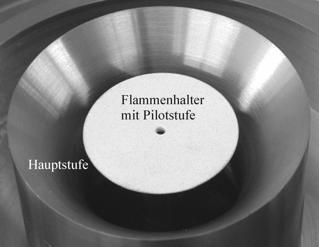
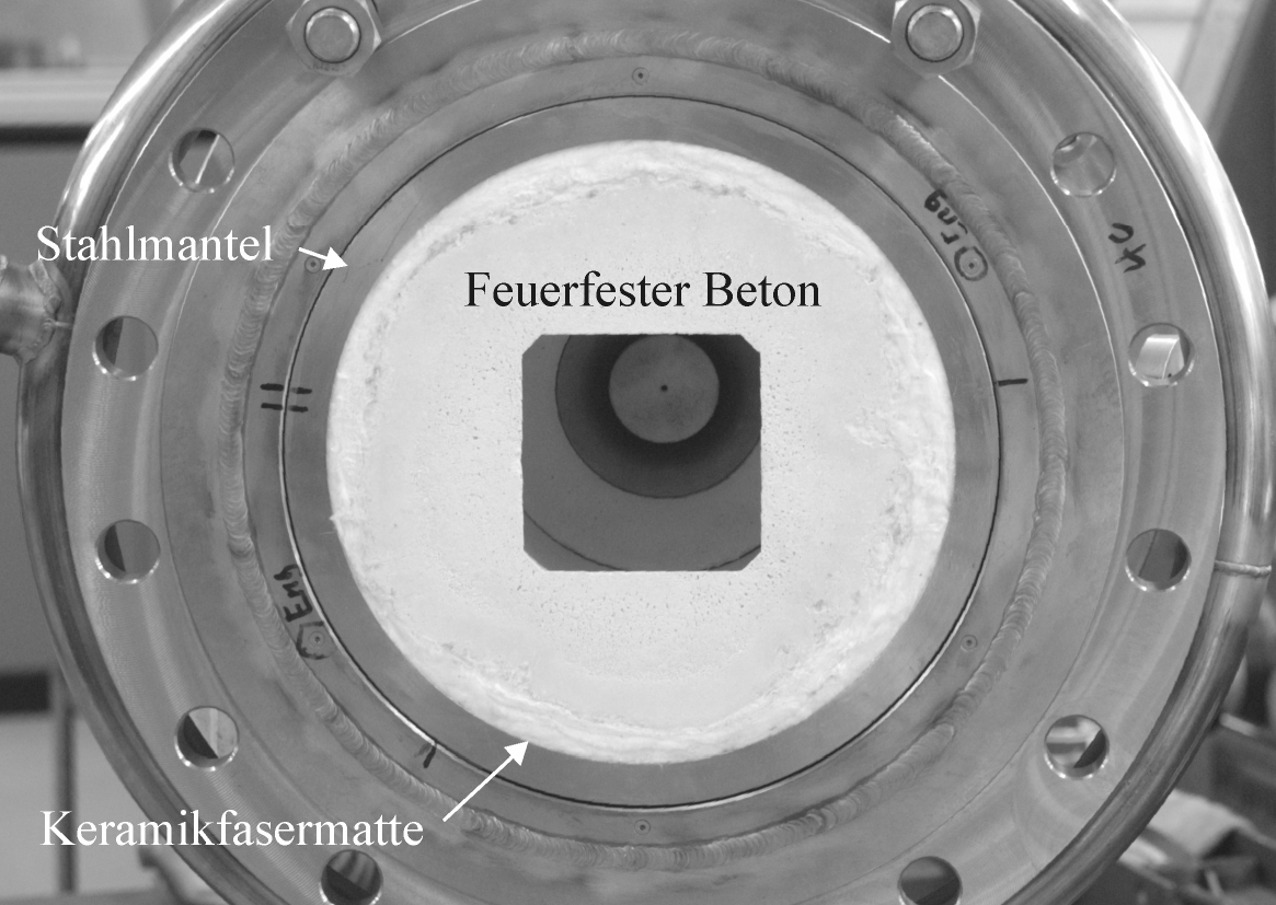
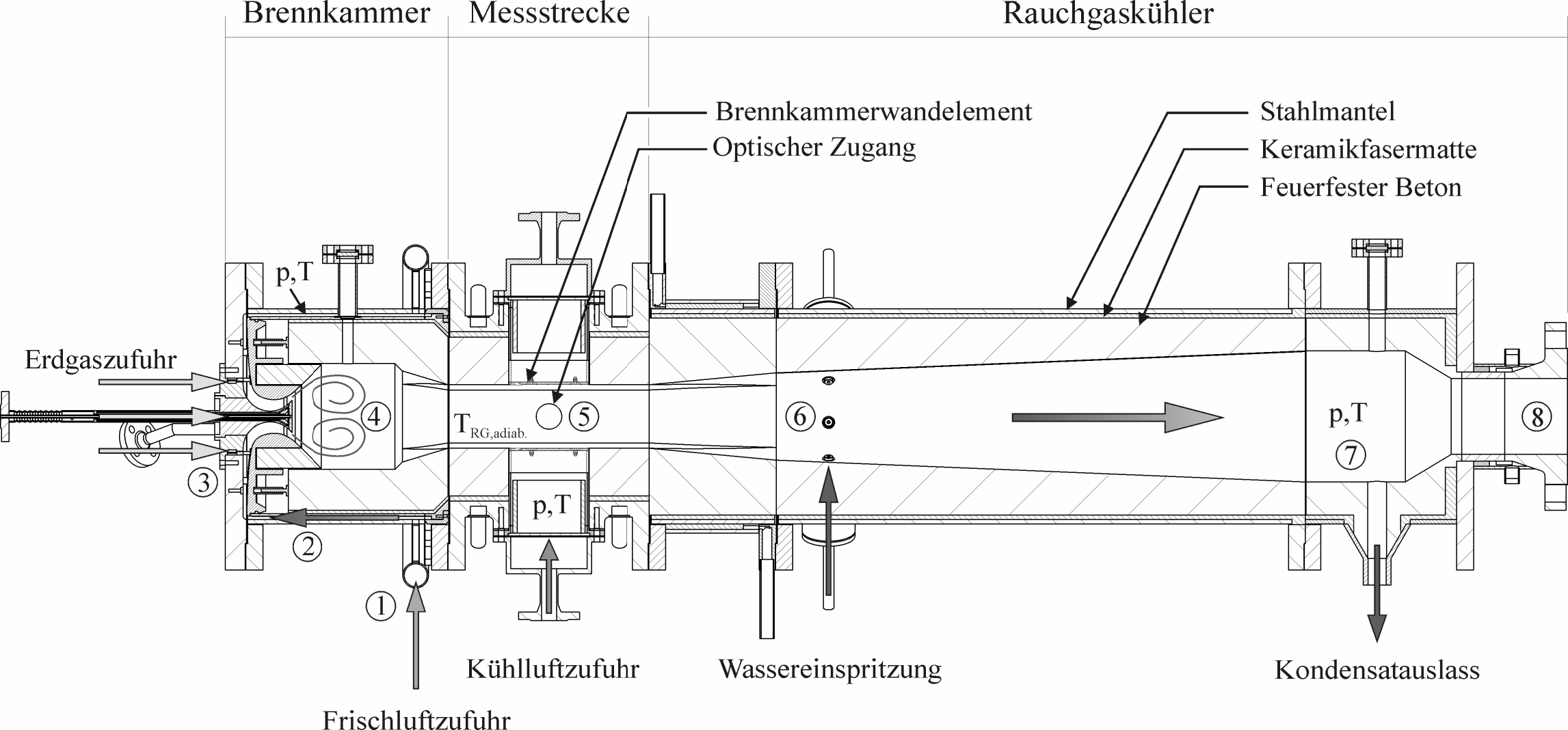
c) Axial section of the modular design (as of 2010), Mende (2010) and Mende et al. (2009)
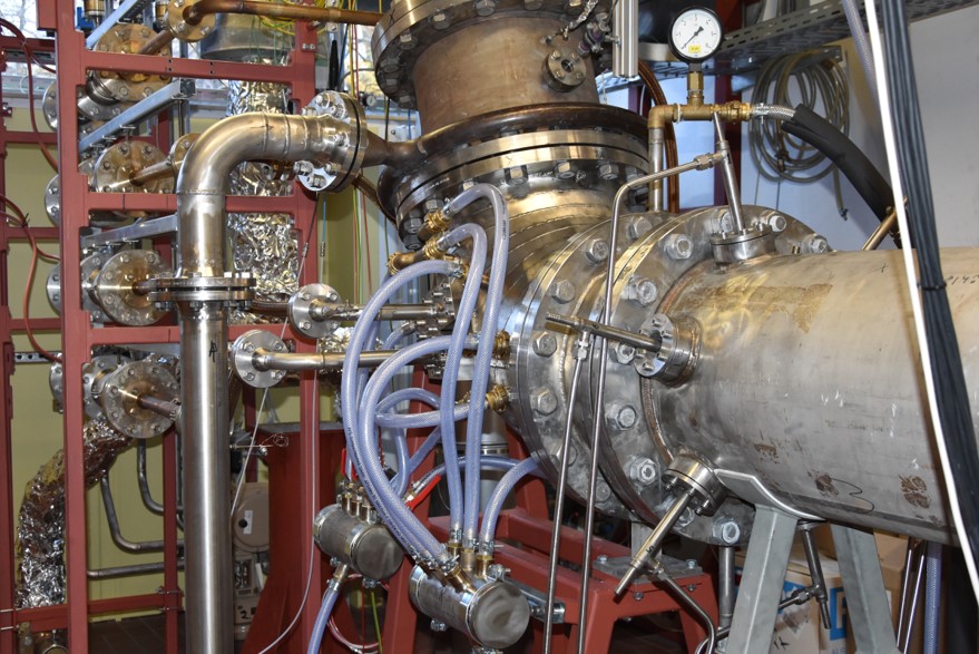
Figure 2: Special features of the thermal cycling test rig
Objectives in the research/industrial sector
- Identification and localization of low-cycle fatigue phenomena as a function of location and time
- Understanding relevant high-temperature damage mechanisms in thermally highly stressed components
- Evaluation of different cooling concepts with regard to their technological applicability and economic success
- Provision of a database for the validation of service life models
Sources
Mende, C.
2010. Logos Verlag Berlin
Mende, C.; Heits, E.; Schulz, A.; Bauer, H.-J.; Wanner, A.
2009. O.M.M.I, 6 (1)