
Challenges
Increasingly stringent legal environmental regulations in civil aviation require the development of efficient and low-emission aircraft propulsion systems. As the formation of pollutants is strongly linked to the combustion process, the design of engine combustion chambers plays a decisive role in the reduction of pollutant emissions. Lean combustion concepts have great potential to significantly reduce combustion emissions from aircraft engines. With existing concepts such as RQL or LDI, the required emission reductions can only be achieved in the short and medium term. In order to meet long-term targets such as Flightpath 2050, a change in fundamental combustion technologies is required.
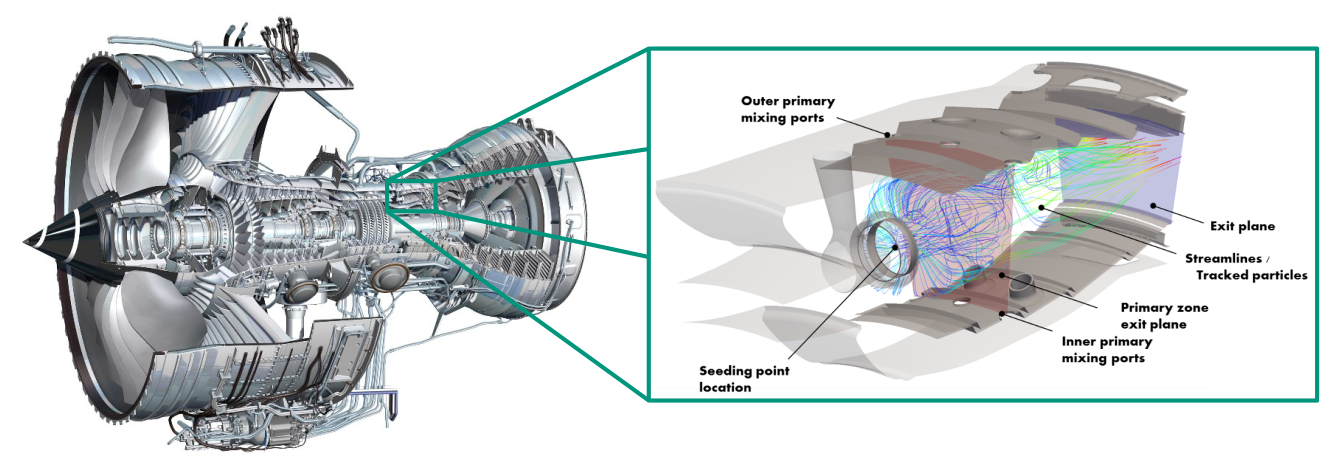
Figure 1: Combustion chamber in an aircraft engine [1, 2]
Investigation of an innovative lean combustion concept
As part of the CHAiRLIFT research project, numerical simulations are being carried out at the Institute of Thermal Fluid Machinery (ITS) to evaluate an innovative lean-burn combustion concept for use in aircraft engines. The inclination of the individual burners in the circumferential direction of an annular combustion chamber increases the stability of the flames through interaction with the neighboring burner. The combination of this helical arrangement of the burners with lean lifted flames promises to achieve long-term emission targets. Based on predictions of aerodynamics and reactive flow, the development of a conceptual combustion chamber geometry will be advanced. The geometry should meet the aerothermal requirements of the lifted flame. The CHAiRLIFT project is part of the European Clean Sky 2 research initiative with the aim of reducing aviation-related emissions.
In a previous research project at ITS, the helical arrangement of the burners in the so-called Short Helical Combustor (SHC) was investigated in detail [1]. The concept offers the possibility of saving installation space and thus weight by axially shortening the combustion chamber. In addition, advantages are achieved in terms of operational stability and emission characteristics. The angular flow through the combustion chamber reduces the number of turbine guide vanes required. This reduces total pressure losses and cooling air mass flows in the first turbine stage and increases the efficiency of the machine. Tilting the burners results in a staggered side wall in the circumferential direction between the individual segments. The interaction of the swirl flow with the side wall is highly complex and its investigation requires further research activities.
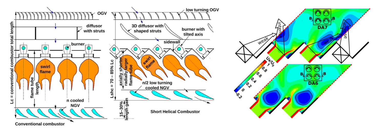
Figure 2: Short Helical Combuster [3]
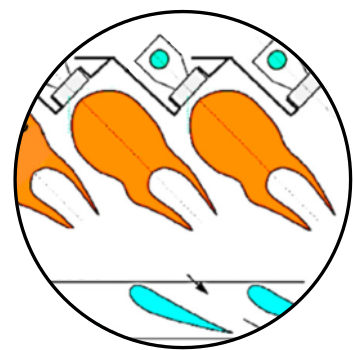
One concept that promises low NOx formation in combustion chambers is the lean lifted flame [2, 3]. This flame does not sit on top of the injector, but is lifted due to only a slight swirl of the combustion air. The flame is stabilized via pronounced outer recirculation zones. There is a premixing zone between the injector and the flame, in which the fuel and combustion air are almost completely mixed. The premixing leads to an even release of heat and reduces nitrogen oxide emissions in lean conditions by reducing temperature peaks in the reaction zone.
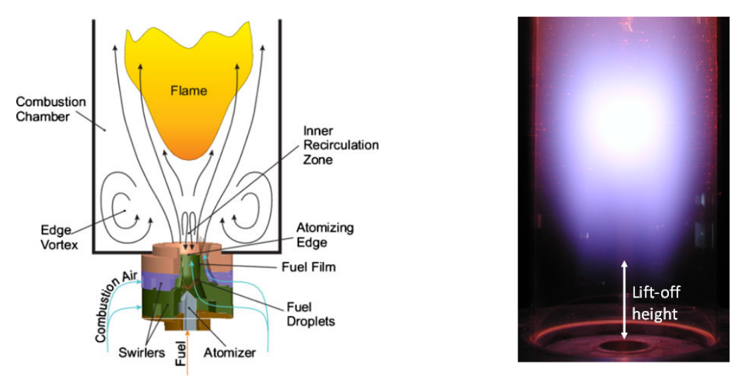
Figure 3: Lifted flame [4, 5]
Objectives in the field of research
The innovative combustion chamber concept presented here makes it possible to meet the requirements of future generations of engines with regard to pollutant emissions. It is based on the combination of an adjusted burner arrangement with lean lifted flames. The objectives of the research project at ITS are as follows:
- Development of a conceptual design for the combustion chamber with angular air supply and lifted flame
- Develop an understanding of dominant flow phenomena and derive design guidelines
- Evaluation of the possibilities for influencing the flow field through systematic parameter variation
- Characterization of the interaction of the swirl flow with the side wall
Sources
[1] Ariatabar, B. (2019): Aerothermal Analysis of an Aeroengine Annular Combustor Concept with Angular Air Supply, vol. 79 of Forschungsberichte aus dem Institut für Thermische Strömungsmaschinen. Logos Publishing House, Berlin. ISBN 978-3-8325-4998-5.
[2] Kasabov, P. (2014): Experimental investigations on lifted flames under pressure. Dissertation, Faculty of Chemical Engineering and Process Engineering. Karlsruhe Institute of Technology (KIT).
[3] Sedlmaier, J. (2019): Numerical and experimental investigation of a lifted flame under pressure. Dissertation, Faculty of Chemical Engineering and Process Engineering. Karlsruhe Institute of Technology (KIT).
Picture credits
[1] Aircraft engine: Rolls-Royce
[2 ] Combustion chamber: Gessel, M. (2015). Proceedings of ASME Turbo Expo 2015. GT2015-42328.
[3 ] Short Helical Combustor: Ariatabar, B. (2016). Journal of Engineering for Gas Turbines and Power. GTP-15-1291.
[4 ] Lifted flame (sketch): Kasabov, P. (2013). Flow, Turbulence and Combustion.
[5 ] Lifted flame (photo): Fokaides, P. (2008). Journal of Engineering for Gas Turbines and Power. GT2007-27126.